
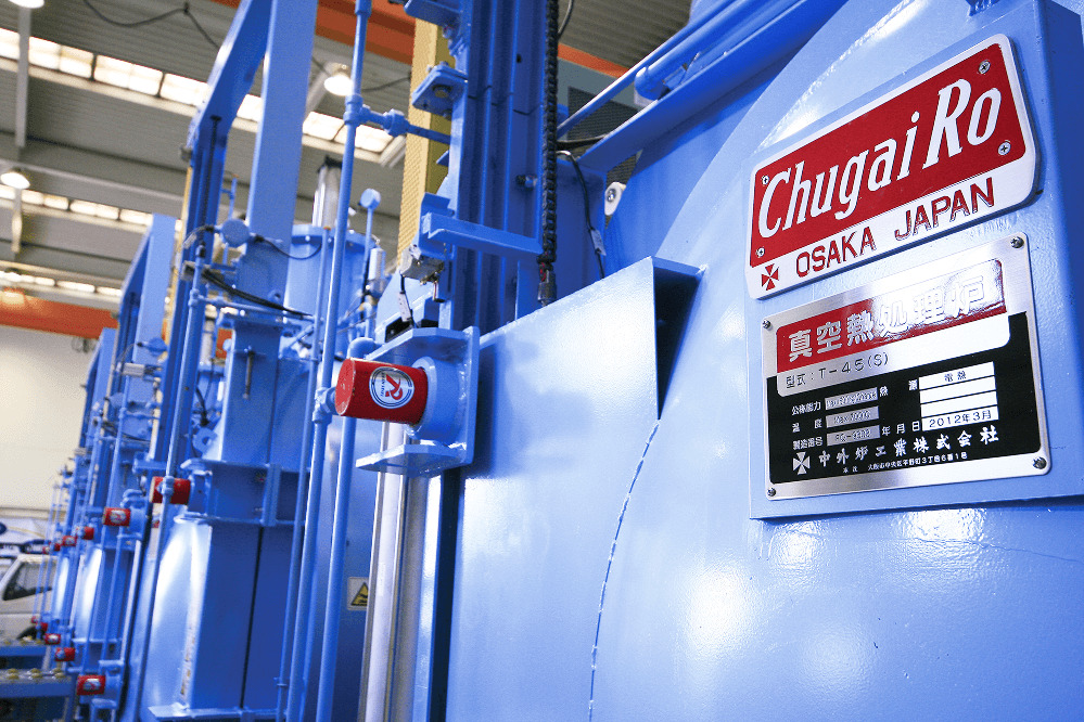
Heat Treatment Furnaces for Parts & Materials
Parts and
Materials Heat Treatment Furnace
Vacuum furnaces, high-temperature furnaces/hot presses, vacuum carburizing, heat treatment of functional materials
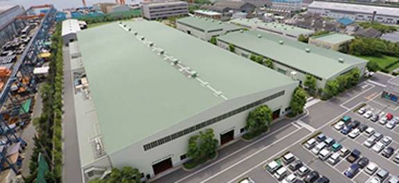
Widely used in film production lines, etc.
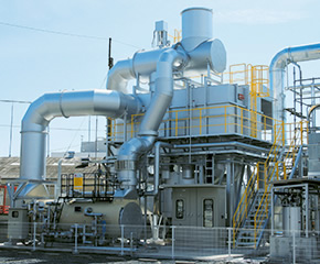
| Product Overview |
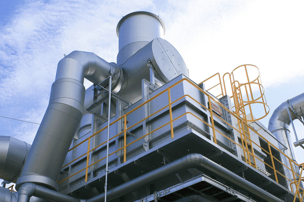
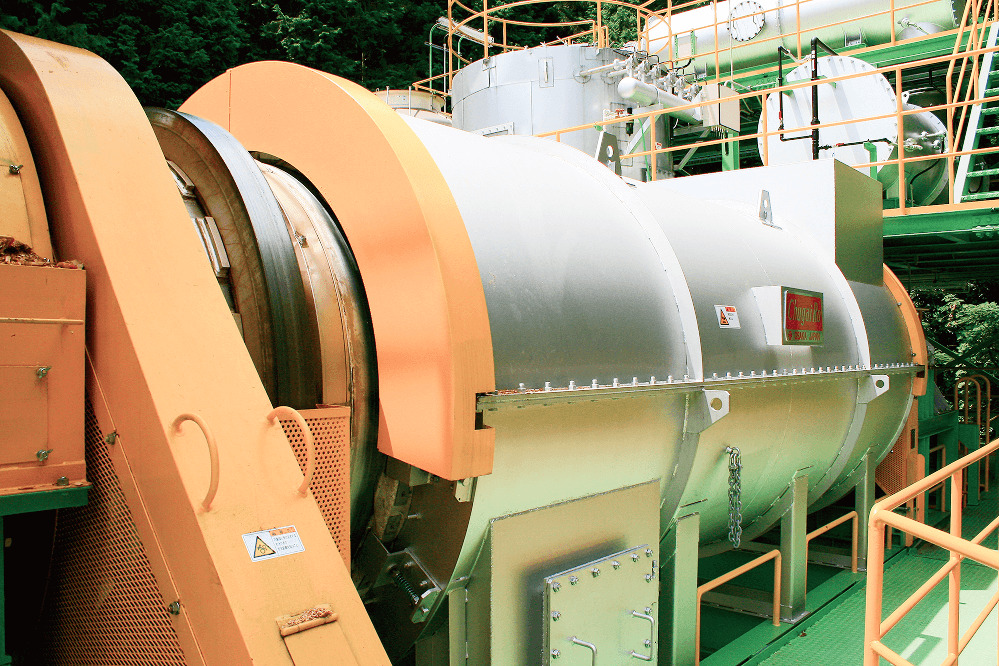
Since the revision of the Air Pollution Control Law in 2004, VOC emission regulations have been promoted in Japan, and many RTO (Regenerative Thermal Oxidizer) systems have been introduced. We have delivered more than 500 RTO units. We have a wide range of models, including rotary types with minimal pressure fluctuation and five-tower types capable of handling large air volumes, and we have extensive experience in energy conservation, including heat recovery using waste heat boilers and regenerative solvent combustion. We also have an independent maintenance department to provide full support. The system consists of 6 to 8 chambers, with special rotary valves that continuously switch the exhaust gas between ascending and descending flows, thus minimizing pressure fluctuations in the production line, and is widely used in film production lines. At the top, the temperature is controlled at 820°C by a heater, and the exhaust gas is heated by the heat storage material as it rises, then cooled and exhausted as it descends while giving heat to the heat storage material. Organic matter is oxidized and decomposed in the upper hot zone and rendered harmless. When switching from up-flow to down-flow, the system is purged with clean gas to prevent unprocessed organic matter that has remained in the lower part from mixing with the purifying gas. |
||||||||
|---|---|---|---|---|---|---|---|---|---|
| processing mechanism (Cycle 1) |
|
||||||||
| processing mechanism (Cycle 2) |
Rotation of the distribution valve switches intake from (1) to (3) to (8) (1) (2), exhaust from (5) to (8) to (4) to (7), and purge from (4) to (3), respectively.Thus, efficient exhaust gas treatment is achieved by continuously switching between intake, exhaust, and purge. |
Heat Treatment Furnaces for Parts & Materials
Vacuum furnaces, high-temperature furnaces/hot presses, vacuum carburizing, heat treatment of functional materials
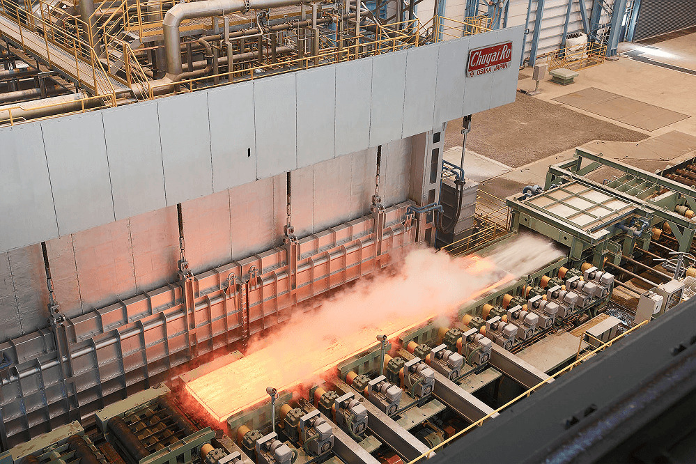
Plant for Steels & Non-Steel Metals
Large-scale heating furnaces, large-scale heat treatment furnaces, transverse induction heating equipment
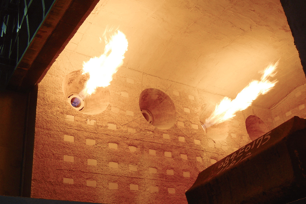
Burner & Combustion Control Equipment
Hydrogen burners, oil and gas burners, gas burners
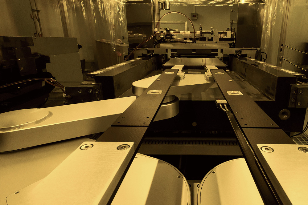
Substrate, Film Coating & Drying Equipment
Heat treatment equipment, precision coatings
Air Pollution Control System
Thermal storage-type exhaust gas treatment system, direct combustion type (direct combustion type), maintenance
Kiln & Environmental Equipment
Multi-tube Rotary Kiln Carbonization System
You can download catalogs in PDF format about Chugai Ro's products and services.
Please use it for sharing and collecting information about the company.